
Understanding how tires are constructed is critical in automotive education, design, and safety. A tire anatomy illustration visually dissects this complex component, making it easier to grasp how tires function from the inside out. Whether you’re preparing a training manual, an educational graphic, or content for an automotive blog, creating your own detailed illustration from scratch can significantly improve comprehension and visual engagement.
This guide not only walks you through the process but also integrates industry insights, professional tool recommendations, and best practices to ensure your diagram meets both educational and technical standards.
What Is a Tire Anatomy Illustration?
A tire anatomy illustration is a labeled visual diagram that reveals the internal structure of a tire—showing components like the tread, belts, bead, and carcass in a clear, accessible format. These illustration design are invaluable in:
- Automotive eLearning platforms: Students can virtually dissect a tire to understand its layered design without needing a physical sample.
- Repair training manuals: Technicians reference these diagrams to better understand repair zones and failure points.
- Marketing and product literature: Tire manufacturers use them to showcase innovations and material quality.
- Engineering documentation: Diagrams accompany technical specifications to describe load tolerance, heat distribution, and structural integrity.
What You Need Before You Start
Creating an accurate and professional tire anatomy illustration requires both technical understanding and the right visual tools.
🔍 Reference Materials
Start by gathering authentic data and visuals:
- OEM tire section diagrams
- Cross-sectional photographs of real tires
- Manufacturer documentation (e.g., Michelin’s “Understanding Tires” guide)
- SAE and ASTM standards on tire construction
These sources ensure technical accuracy and industry alignment.
🛠 Recommended Tools
Choose your tools based on the complexity and purpose of the illustration:
| Purpose | Recommended Tool | Why It Works |
|---|---|---|
| Vector/print | Adobe Illustrator | Sharp lines, scalable diagrams |
| Digital sketching | Procreate or Autodesk SketchBook | Ideal for stylus work |
| Photo-editing | Adobe Photoshop | For blending textures (photobashing) |
| 3D modeling | Fusion 360, SolidWorks, Blender | Precision and interactivity |
Tip: Adobe Illustrator’s vector tools ensure your illustration remains crisp and editable across various screen sizes—ideal for responsive web design and high-res print.
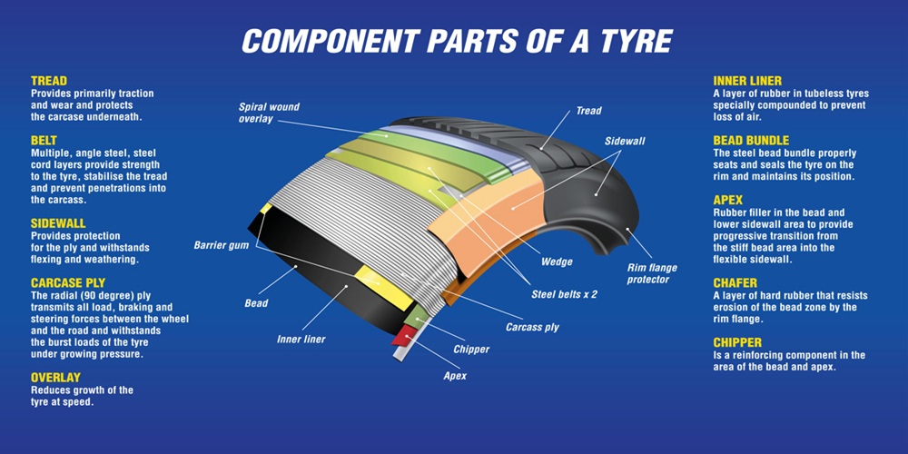
Understanding Tire Anatomy: Key Components
Before illustrating, understand each part’s form and function. Here’s a quick breakdown:
- Tread: The outermost layer; provides traction. Composed of various rubber compounds based on use (e.g., winter, performance).
- Sidewall: Protects the internal structure; provides information like size and max load.
- Bead: A steel-reinforced ring ensuring the tire sits tightly against the rim.
- Belts: Steel or aramid fabric layers that reduce deformation and enhance tread stability.
- Cap Ply: Often found in performance tires; stabilizes the tire at high speeds.
- Carcass Ply: The main structural layer, usually made of polyester or nylon.
- Inner Liner: A rubber compound that acts as an air sealant inside tubeless tires.
- Shoulder: Transition between tread and sidewall; aids in cornering stability.
📌 Pro Tip: When illustrating, emphasize the unique roles of each part—particularly where structural integrity and safety depend on accurate representation.
Step-by-Step: How to Create a Tire Anatomy Illustration
Here’s how to build a high-quality tire diagram from scratch.
Step 1: Sketch the Base Shape
Draw a basic circular or oval shape depending on your view (cross-section or angled). Maintain symmetry by using guides.
Step 2: Layer Key Structural Zones
Divide the shape into:
- Outer tread band
- Sidewall
- Inner liner
- Belts and plies
Photobashing Tip: Lightly overlay real textures (e.g., tire tread or steel mesh) into your base to simulate materials.
Step 3: Illustrate Each Component
Use varied line weights to show depth. Reserve heavier lines for outer features and lighter strokes for internal layers. If illustrating in CAD, use dashed or color-coded boundaries for clarity.
Step 4: Label with Precision
- Use clean, readable fonts (Arial, Open Sans, Helvetica).
- Position labels with leader lines for neatness.
- Optionally add a color-coded legend.
Step 5: Add Visual Enhancements
- Apply gradients to suggest depth.
- Use transparent overlays to show inner components in a 3D-style view.
- Highlight critical components (bead, belts) with bold outlines.
Step 6: Export and Optimize
- Save in multiple formats: SVG (web), PNG (presentations), PDF (print).
- Include a text description for accessibility and SEO.
- Validate component names against manufacturer data or standards.
Going Deeper: Functional Relevance of Key Parts
Beyond their names, here’s why each component matters:
- Steel belts provide rigidity and reduce rolling resistance, improving fuel economy.
- The inner liner eliminates the need for a tube, increasing durability.
- Cap plies resist centrifugal force at high speeds—critical in sports or performance tires.
- The bead’s tight seal prevents air leaks and tire slippage, especially under lateral G-forces.
Variations in Tire Anatomy: Radial vs. Bias-Ply
Not all tires are built the same.
| Feature | Radial Tires | Bias-Ply Tires |
|---|---|---|
| Ply Angle | 90° to tread | 30–45° crisscross |
| Ride Quality | Smoother | Stiffer |
| Application | Modern vehicles | Specialty, vintage, off-road |
Your illustration should match the tire type. Add side-by-side comparisons for clarity when necessary.
Common Use Cases for Tire Anatomy Illustrations
- Training courses: To teach tire construction in automotive tech schools.
- Safety campaigns: To explain wear, blowouts, or structural failure.
- Marketing brochures: To highlight high-end materials or design differences.
- Product manuals: To show how to properly install, mount, or inspect.
💡 Hands-on Tip: Encourage learners to handle a discarded tire while referring to your illustration for real-world context.
Common Mistakes to Avoid
❌ Mislabeling components (e.g., calling the carcass a cap ply)
❌ Overcrowding with too many labels
❌ Using non-standard terminology or inconsistent styling
❌ Omitting key structural layers (e.g., belts in radial designs)
📌 Always cross-reference against technical documents from tire OEMs or industry standards (e.g., SAE J2530).
Examples of Tire Anatomy Illustration
Here are suggested image types to include:
- Basic cross-section With Labels for Each Major Component
- Color-coded Layer View to Distinguish Materials
- 3D Exploded View for Dynamic Presentations
- Cross-ply Vs Radial Comparison Chart
Basic Cross-Section With Labels for Each Major Component

Color-Coded Layer View to Distinguish Materials
3D Exploded View for Dynamic Presentations

Cross-Ply Vs Radial Comparison Chart

Resources and References
Conclusion
Creating a tire anatomy illustration from scratch combines technical knowledge with design skill. Whether for education, marketing, or product development, a clear, accurate, and visually engaging diagram enhances communication and understanding.
As with any technical illustration, accuracy is critical—not just for clarity, but for safety and credibility. Use trusted references, apply visual best practices, and always test your work with your target audience.
🎯 Final Tip: Encourage feedback from educators or engineers to refine your diagram. Accuracy builds trust—and trust builds authority.
FAQs
1. What is a tire anatomy illustration?
A tire anatomy illustration is a labeled diagram showing the internal parts of a tire—like tread, belts, and bead—to explain how it works and supports vehicles.
2. Why are tire anatomy diagrams important?
They help students, engineers, and technicians understand tire construction, safety, and repair by visualizing each component and its function, from traction layers to structural supports.
3. What tools are best for creating a tire diagram?
Use Adobe Illustrator for vector work, Photoshop for textures, and Fusion 360 or Blender for 3D views to ensure clarity, scalability, and technical accuracy in your design.
4. What are the main parts shown in a tire diagram?
Key parts include tread, sidewall, bead, steel belts, cap ply, carcass ply, shoulder, and inner liner—each serving a unique purpose in traction, safety, and durability.
5. How do radial and bias-ply tires differ?
Radial tires have 90-degree plies for smoother rides, while bias-ply tires have angled, crisscrossed plies—common in vintage or off-road applications due to their stiffer design.
6. What are common mistakes in tire illustrations?
Mistakes include mislabeled parts, overcrowded labels, missing key layers, and inconsistent terms. Always cross-check with OEM or SAE standards for accurate, professional-quality diagrams.
7. Where can I find reliable tire structure references?
Check resources like Michelin’s “Understanding Tires” guide, SAE standards, ResearchGate studies, and OEM diagrams to ensure your tire illustration is both accurate and industry-compliant.
4. What makes a tire anatomy illustration professional-grade?
Top illustrators use precise line work, layered views, and clear labels to show internal structures—combining technical accuracy with engaging visuals for learning, marketing, or repair documentation.